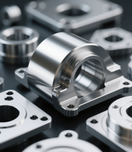


Efficient CNC design is key to balancing functionality, cost, and production efficiency. Following these guidelines helps avoid common design challenges, enhance manufacturability, and streamline production processes. From minimizing thin walls and deep cavities to setting reasonable tolerances, each recommendation in this solution simplifies machining and ensures quality.
Avoid Excessively Deep Cavities and Grooves
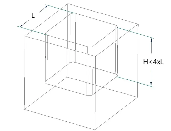
The depth of cavities and grooves is typically related to the tool diameter for machining internal fillets. A good rule of thumb is to keep cavity depth within 3-4 times the tool diameter, or groove depth less than 4 times the feature width.
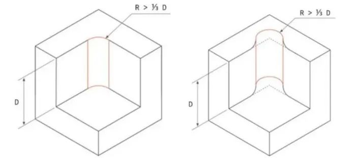
Design Larger Internal Fillets
In CNC machining, any internal cut produces a fillet with a radius equal to half the tool diameter. Milling with small tools takes longer, so it’s recommended that fillet radii be larger than 1/3 of the machining depth. Ideally, design the largest possible internal fillets and ensure all internal edges use the same radius, allowing a single tool to complete the machining.
If large fillets are impossible due to design requirements (e.g., mating with a square part), consider the following alternative design:
Avoid Thin-Wall Structures
Thin walls are prone to vibration during machining, especially for tall features. Recommended minimum wall thickness: 0.5-0.8 mm for metal parts, and 1.0-1.5 mm for plastic parts. If walls support tall features, increase thickness appropriately. For unavoidable thin walls, combining CNC machining with sheet metal riveting is a more cost-effective choice. Additionally, for thin plates ≤6 mm thick, design them to match standard sheet metal thicknesses.
Avoid Deep Holes
For both blind and through holes, recommend hole depth ≤4 times the diameter, with a minimum diameter of 1 mm. Prioritize standard hole sizes. Standard drill bits machine holes efficiently and accurately, while non-standard holes require end mills, increasing costs. Note: Blind holes drilled with standard bits have a 135° conical bottom, while those milled with end mills have flat bottoms.
Use Standard Threads
Prioritize standard thread sizes—larger threads are easier to machine. Thread length should not exceed 3 times the hole diameter. For blind-hole tapping, leave at least 1/2 the hole diameter of extra space at the bottom. For large-diameter blind-hole threads or threaded posts, add a relief groove at the thread bottom to ensure full tightening. Consider inserts like thread coils or copper nuts for durability in materials like aluminum or plastic, which are also easier to install.
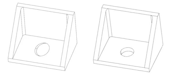
Minimize Clamping Times
To reduce machining costs, minimize part clamping times—ideally, complete all machining in one setup. If the part structure requires machining from multiple orientations, it may need multiple clamps or multi-axis CNC machines, increasing costs.
Example: The left diagram below requires two clamps, while the right diagram completes machining in one clamp.
Avoid Non-Functional Aesthetic Features
Non-functional aesthetics like surface grinding, polishing, anodizing, painting, or plating increase post-processing labor costs. Avoid such designs unless necessary to reduce machining time and costs.
Avoid Too-Small Features
Most CNC machines have a minimum tool diameter of 2.5 mm. Smaller tools are more prone to breakage and require slow feed rates and light cuts, prolonging machining time. Avoid tiny features unless design-critical. The VIC CNC machine can machine down to 0.3 mm tool diameter, achieving internal fillets as small as R0.15 mm for intricate features.
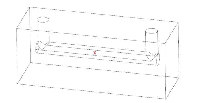
Avoid Unmachinable Features
Not all design features are CNC-machinable. For example, fully enclosed holes and U-shaped slots cannot be machined directly. Enclosed holes should be designed as blind holes first, then sealed with threaded assemblies on the top. U-shaped slots require split-part machining.
Avoid Tiny or Raised Text
For part numbers or logos, avoid complex lettering. Electrochemical etching or laser engraving are better options. If milling text is necessary, use recessed (not raised) fonts with moderate size and depth ≤0.3 mm.
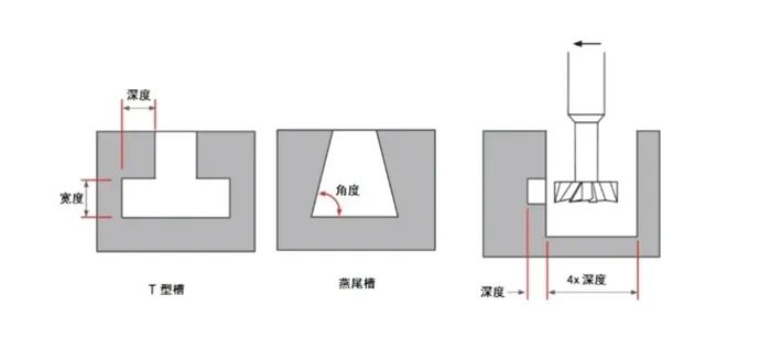
Undercut Design
Undercuts typically include T-slots and dovetail grooves, both requiring T-shaped tools. Standard dovetail angles are 45° or 60°. Ensure the top width of a T-slot is larger than the T-tool diameter—typically, the top width should be over 4 times the undercut depth.
For through-type T-slots/dovetails, side entry is allowed. For circular dovetails (e.g., for O-ring assembly), create a relief hole at the dovetail’s bottom maximum width for tool entry.
Avoid External Radius on Part Edges
To prevent scratches during handling or assembly, design external radiuses (R) or 45° chamfers (C). External R corners require multiple passes with ball-end mills or custom tools, while 45° C chamfers can be machined in one pass with a chamfer tool. Prioritize 45° C chamfers for edge deburring.
Reasonable Tolerance Design
Unspecified tolerances for metal parts typically meet ISO2768-fH, and for plastic parts, ISO2768-mK. Tighter tolerances increase machining difficulty and time. Optimize production efficiency by specifying strict tolerances only when necessary.
For assembly tolerances, metal parts often use Grade 7 (e.g., H7 hole basis or h7 shaft basis). Smaller tolerance grades mean higher precision and greater machining difficulty.