


From chairs to space stations, technology permeates our world—and the shaft, invented alongside the wheel, remains the backbone of machines. Functionally, shafts transmit torque, momentum, and motion to connected components. While diverse in type, this article focuses on spline shafts, exploring their classifications, materials, and manufacturing processes.
What Is a Spline Shaft? Definition and Core Mechanics
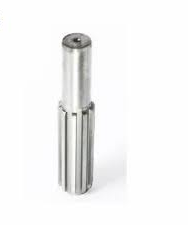
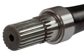
A spline shaft is a central machine component featuring grooved ridges on its mating surface. It facilitates torque transmission and alignment, preventing wear or slippage by distributing loads evenly.
Spline Shaft vs. Keyway Shaft: When to Choose Which?
- Spline Shafts: Ideal for high-precision torque management.
- Keyway Shafts: Suited for low-torque, cost-sensitive applications.
Torque Capacity
Design impacts torque tolerance: spline shafts typically handle 30% more torque than keyway shafts, as shown in shear load and fatigue tests.
Alignment Precision
Backlash in robotics and CNC equipment affects alignment. Spline shafts eliminate backlash, ensuring consistent precision.
Key Parameters of Spline Shafts
- Tooth profile (e.g., involute)
- Root diameter
- Pressure angle (30° is standard for industrial use)
5 Key Functions of Spline Shafts in Modern Machinery
- Slip-Free Torque Transmission
Efficiently transfers power to connected wheels, such as in automotive drivetrains. - Axial Movement Regulation
Linear actuators rely on spline shafts for motion alignment. - Vibration Damping via Load Distribution
Even load distribution reduces vibration. - Precision Alignment for CNC Equipment
Maintains tight tolerances during high-speed CNC operations. - Fail-Safe Disengagement
Disengages under overload to protect the system.
Types of Spline Shafts: A Designer’s Guide
Selection depends on application needs (load type, speed, etc.).
Involute Splines (DIN 5480 / ISO 4156)
Standardized by ISO 4156 and DIN 5480, involute splines are industrial mainstays due to:
- Self-alignment
- 30° pressure angle
- Gradual load transfer
Applications:
Automotive transmissions, industrial gearboxes, aerospace actuators.
Why 30° Pressure Angle Is Ideal:
Balances load capacity and fatigue life for 80% of industrial uses.
Straight-Sided Splines (SAE J498)
Simple in structure with flat tooth profiles, these splines offer lower load distribution efficiency.
- RPM limit: Best below 500
- Cost-effective design
Applications:
Agriculture (tractor shafts), hydraulic pumps, old industrial equipment.
Serrated Splines (Military Spec MIL-S-8879)
Featuring 45° angled teeth, these withstand axial impact loads, extreme vibrations, and misalignments.
Applications:
Black Hawk helicopter rotor shafts, missile launch track actuators.
Ball Splines
Designed for linear motion, ball splines offer:
- Minimal backlash (hardened rolling elements)
- 90% less friction than keyed shafts
- 10x longer life in high-cycle applications
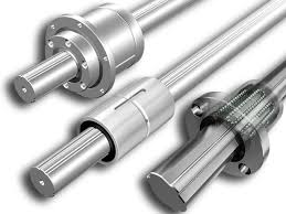
Applications:
Semiconductor wafer processors, medical robots, 6-axis CNC trunnion tables.
Crown Splines
With a barrel-shaped profile, crown splines:
- Self-correct angular motion
- Distribute loads evenly
- Extend service life by 300%
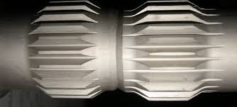
Applications:
Wind turbine gearboxes, marine propulsion shafts, mining conveyor drives.
How to Manufacture Spline Shafts: Step-by-Step
Step 1: Design Validation and Tolerance Mapping
- 3D FEA simulation (ANSYS) to verify stress distribution under max torque
- Tolerance stack-up analysis (ISO 4156 Grade 5 for thermal expansion)
- Spline profile selection (involute DIN 5480 or straight SAE J498)
- Tools: Gear design software (KISSsoft, Romax)
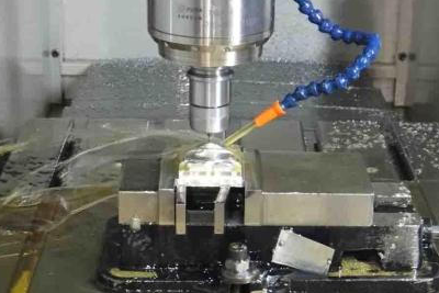
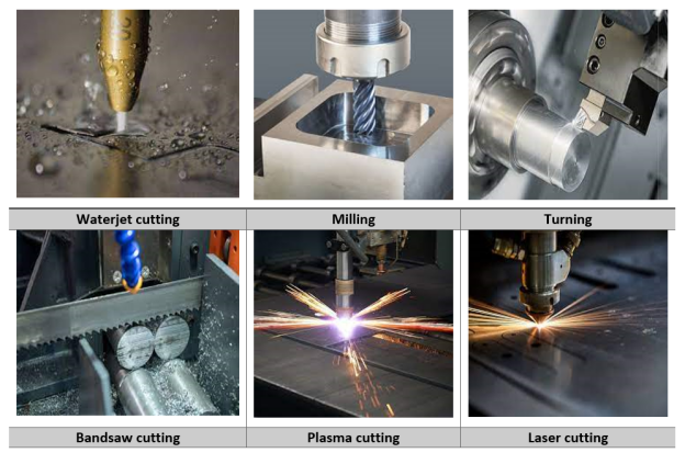
Step 2: Material Preparation and Pre-Machining
- Material Cutting: Steel bars cut by cutting machines.
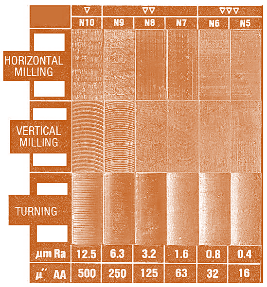
- Turning: CNC lathes for precision (diameter: ±0.05mm, surface finish: 3.2μm).
- Drilling: For center-to-center machining.
- Annealing: Relieves stress to prevent deformation.
Step 3: Main Spline Formation
- Broaching: Tungsten carbide broaches at 5–15 m/min (DIN 1415 standard, DIN 7 precision).
- Hobbing: CNC hobbing machines (HCC cutters, AGMA 10 tolerance).
- Grinding: For hardened shafts (CBN wheels, 0.4μm surface finish).

Step 4: Post-Processing and Surface Enhancement
- Heat Treatment: Surface hardening.
- Shot Peening: Improves fatigue life.
- Coating: DLC for wear resistance.
Step 5: Quality Assurance and Testing
- CMM measurement (tooth profile: ±0.005mm)
- Gear rolling test (DIN 3961 for composite error)
- Torque test (30% higher capacity than key shafts)
- Certifications: ISO 9001, PPAP for automotive clients.
Common Spline Shaft Standards: SAE, DIN, ISO
Standards guide material selection, manufacturing, and post-processing for industry compatibility.
- SAE J500 (Automotive) vs. DIN 5480 (EU Machinery):
SAE J500 applies to stainless steel in automotive, while DIN 5480 governs mechanical power transmission. - Tolerance Differences:
SAE allows ±0.0002″, DIN Grade 0.05 allows ±5mm. - Metric vs. Imperial:
Imperial splines dominate North America; metric prevails globally.
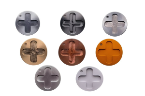
Spline Shaft Material Selection: From Aluminum to Superalloys
General Industrial Use
- Alloy Steel (4140/4340):
Low-to-medium carbon alloys, cost-effective with high strength and toughness.
Drawback: Corrosion-sensitive without chromium. - Stainless Steel (17-4PH):
Precipitation-hardened martensitic steel, corrosion-resistant and weldable.
Drawbacks: Difficult to machine, limited high-temperature performance.
Lightweight Applications
- Aerospace Aluminum (7075-T6):
60% lighter than steel, high strength-to-weight ratio.
Drawback: Lower fatigue limit than steel. - Titanium Alloy (Ti-6Al-4V):
Strong, lightweight, and biocompatible.
Drawbacks: Poor wear resistance, risk of hydrogen embrittlement.
Extreme Conditions (High-Temp/Corrosion)
- Nickel-Based Superalloy (Inconel 718):
Excellent high-temperature and corrosion resistance.
Drawbacks: Segregation in large castings, high cost. - Cobalt-Chromium Alloy (Hastelloy C276):
Superior corrosion resistance and high-temperature strength.
Drawbacks: Limited supply, difficult to machine.
Spline Shaft Design: 7 Rules to Prevent Failure
- Use AGMA Stress Calculations to avoid tooth fracture (calculate root bending stress and flank contact stress).
- Set Fillet Radius to 0.25× Modulus to prevent cracks, extending life by 400%.
- Achieve Ra 0.8µm Surface Finish via grinding to enhance fatigue life.
- Cut 45° Helical Grooves to reduce adhesive wear by 60%, critical in transmissions and pumps.
Spline Shaft Applications: Industry-Specific Solutions
- Automotive: 26-spline shafts handle 650 Nm, while 24-spline shafts suit older, cost-sensitive designs.
- Aerospace: Self-lubricating splines in jet engines resist grease contamination across -60°C to 300°C.
- Robotics: PEEK-coated splines ensure silent operation and corrosion resistance.
Maintenance and Repair Techniques
- Resplining vs. Replacement:
Respline for minor wear or non-critical applications (saves 50% cost vs. replacement). Replace if roots are cracked or loads are critical. - Wear-Resistant Coatings:
DLC and nickel-Teflon are common; DLC outperforms nickel-tungsten in critical uses.
Conclusion
Spline shafts are integral to mechanical systems, enabling efficient torque and motion transmission. By selecting the right material, type, and design, engineers can optimize performance for real-world applications, ensuring reliability and longevity.