


Press fit, also known as interference fit, is a classic assembly technique where a slightly larger component is pressed into a slightly smaller mating part, forming a secure connection through friction. This complete guide to press fit tolerances is sure to provide valuable insights!
What Are Press Fit Tolerances?
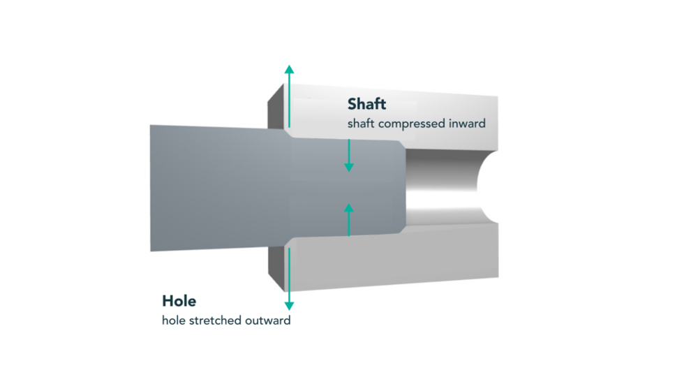
Press fit tolerances refer to the slight dimensional difference between a shaft and its mating hole that creates an interference fit. The shaft is slightly larger, so when pressed into the hole, friction holds the parts tightly together. This technique achieves a secure assembly without the need for adhesives or fasteners.
Interference Fit, Transition Fit, and Clearance Fit
Based on the dimensional relationship between the shaft and hole, engineering fits are categorized into three types:
| Fit Type | Description | Typical Applications |
|---|---|---|
| Clearance Fit | Shaft < Hole; allows movement. | Rotating or sliding components |
| Transition Fit | Shaft ≈ Hole; light force fit. | Precise alignment, detachable |
| Interference Fit | Shaft > Hole; secure, permanent fit. | Bearings, gears, hubs |
Shaft Basis vs. Hole Basis Systems (ISO 286 Overview)
ISO 286 defines tolerance codes: uppercase letters (e.g., H) indicate holes, and lowercase letters (e.g., p) indicate shafts. A hole basis system (e.g., H7/p6) keeps the hole size constant while varying the shaft to control the fit. A shaft basis system (e.g., h6/P7) does the opposite.
Empirical Ranges for Light, Medium, and Heavy Press Fits
There are differences between light, medium, and heavy press fits:
| Fit Type | Interference (% of Diameter) | Typical Assembly Method | Notes |
|---|---|---|---|
| Light Press Fit | 0.05% | Manual or arbor press | Easy to assemble, detachable |
| Medium Fit | 0.1-0.2% | Mechanical press | Standard for rotating components |
| Heavy Fit | 0.3-0.6% | Shrink fit method | Permanent, high strength |
Key Factors Affecting Press Fit Tolerances
Not all interference fits perform the same. The following factors influence the appropriate amount of interference and the effectiveness of the interference fit:
Material and Mechanical Properties
Different materials affect the required interference. Harder, stronger materials can withstand greater interference.
Material Modulus and Yield Strength
Harder, stronger materials can tolerate more interference before deforming or yielding, while softer materials may deform or creep even with small interference. Elastic modulus (Young’s modulus) and yield strength are two key properties:
| Material | Elastic Modulus (GPa) | Yield Strength (MPa) |
|---|---|---|
| Steel Plate | 210 | 250-400 |
| Aluminum 6061-T6 | 69 | 275 |
| Plastic (e.g., PC) | 2-4 | 50-70 |
Geometric Accuracy of Mating Parts
Theoretical interference assumes parts are perfectly round, straight, and smooth. Real-world geometry may have deviations:
Surface Roughness
Roughness affects friction and effective interference. Recommended Ra: 0.8–3.2 µm.
Roundness
Non-roundness reduces full contact rate. Use reaming/grinding to improve accuracy.
Taper
Tapered holes/shafts can cause uneven fitting. Cylindrical geometry is recommended.
Thermal Effects During Assembly
Temperature changes can make or break a press fit (literally!). Engineers often use this property for assembly, as materials expand when heated and contract when cooled.
Temperature Variations in Assembly
Shrink fits use cooling (shaft) or heating (hole) to simplify assembly. Materials with higher coefficients of thermal expansion (CTE), such as aluminum, require special attention.
Surface Condition and Interface Chemistry
The condition of mating surfaces affects friction during assembly and long-term behavior:
Lubrication
Lubricants reduce friction during assembly but do not affect retention force.
Cleanliness
Remove debris, burrs, and oxides to ensure proper fitting.
Oxide Layers
Oxides may interfere or cause wear. Clean surfaces before assembly.
How to Calculate Press Fit Interference?
To design an interference fit, we usually need to estimate the stress or pressure generated by the interference. Here we will delve into the details:
Basic Formula: Δ = (δ × D) / E
This formula estimates the required interference (Δ) based on material strain (δ), nominal diameter (D), and modulus (E). It helps estimate how much interference is needed to generate the desired stress level without exceeding material limits.
Hole H7 with Shaft p6 / n6 / s6
The table below shows typical interference ranges for ISO fits using a 50 mm nominal diameter:
| Fit Type | Hole Diameter Range (mm) | Shaft Diameter Range (mm) | Interference Range (mm) |
|---|---|---|---|
| H7/p6 | 50.000-50.025 | 50.026-50.042 | 0.001-0.042 |
| H7/n6 | 50.000-50.025 | 50.012-50.027 | –0.013–0.027 (may be transitional) |
| H7/s6 | 50.000-50.025 | 50.035-50.050 | 0.010-0.050 |
Calculator Recommendations: Pros, Cons, and Pitfalls
Online press fit calculators simplify tolerance checks. They are fast, but users must ensure correct unit input and understand the shaft/hole basis fit direction. Always double-check calculator outputs against standards.
Standards and Tolerance Tables for Practical Use
Here are detailed tables of some standards and tolerances:
ISO 286 Fit Bands for Diameters 5 mm – 80 mm
For a Ø50 mm nominal size, the H7 tolerance is +0.000 to +0.025 mm. The shaft tolerance (p6) is +0.026 to +0.042 mm.
ANSI B4.1 Interference Classes (FN1–FN5) Explained
| Fit Class (ANSI) | Interference (inches/inch) | Application Areas |
|---|---|---|
| FN1 | 0.0005-0.0010 | Light press, thin walls |
| FN3 | 0.0015-0.0025 | Standard interference |
| FN5 | 0.004-0.006 | Heavy/heat shrink fits |
Bearing Housing Press Fit Charts
General rule: 0.0004–0.0010 × diameter for interference. For a Ø50 mm bearing housing: approximately 0.02–0.05 mm interference ensures retention without preload deformation.
Design for Manufacturability: CNC, Molding, and Die Casting
Even with perfect tolerance specifications, high manufacturing or assembly infeasibility can lead to product failure. Here are some manufacturing considerations for interference fits:
Machined Fits: Precision Limits of Boring vs. Reaming
Reaming is ideal for H7 hole fits (high precision and repeatability). Grinding may be needed for tighter fits. Avoid using drills for final fit dimensions.
Injection-Molded or SLS Plastic Press Fits
Molded holes may have ±0.1 mm tolerance. For critical fits, post-machining (reaming) or oversizing during design is required.
Die-Cast Press Fit Guidelines
Post-drilling and reaming are needed to eliminate draft angles and achieve precise holes. Material brittleness limits maximum interference.
Press Fit Assembly Methods and Required Force
Manual Press vs. Hydraulic Press – Force Chart by Diameter
Larger diameters or tighter fits require hydraulic presses. Manual presses suffice for small sizes/light fits.
Thermal Methods: Liquid Nitrogen Shrink Fits, Hot Plate Expansion
Cooling the shaft and heating the hub reduces insertion force. Allow parts to balance slowly after fitting to avoid stress.
Monitor and Record Peak Force for Quality Traceability
In critical components, measure insertion force to ensure tolerance targets and process consistency.
Press Fit Problems and Solutions
Galling and Material Transfer
Use finer surface finishes (Ra < 2 µm) and lubricants to prevent metal pick-up.
Interference Loss Over Time
Plastics and soft metals may relax. If creep is expected, use knurling or adhesives to enhance the fit.
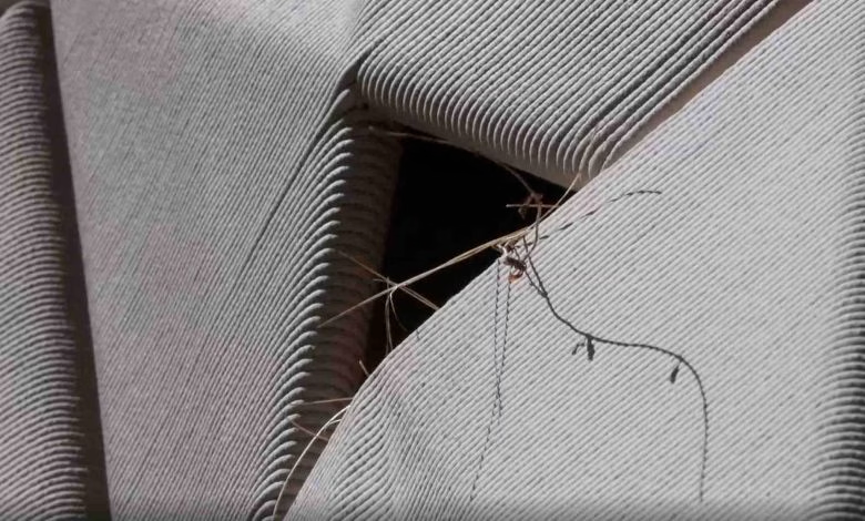
Hub or Flange Cracking
Avoid sharp corners; ensure chamfers and select appropriate fit classes.
Conclusion
Press fit tolerances are crucial for reliable mechanical assemblies. Choose the right fit class, verify material properties, ensure surface quality, and use appropriate pressing or thermal methods. By focusing on these details, engineers can achieve durable, high-precision interference fits.
For more information, please contact Debaolong Seiko. You are also welcome to upload your designs to Debaolong Seiko for a quotation.