


CNC stepover refers to the distance between consecutive toolpaths of a cutting tool in computer numerical control (CNC) machining. This critical parameter influences both part machining time and surface finish. Different machining operations require varying stepover values, with optimal selections depending on the tool and workpiece.
This guide outlines CNC stepover and explains its application in CNC milling—a process that precisely removes material from a raw workpiece to create parts. Other CNC operations, such as turning and grinding, use similar parameters but under different names and with distinct calculations.
What Is Stepover in CNC?
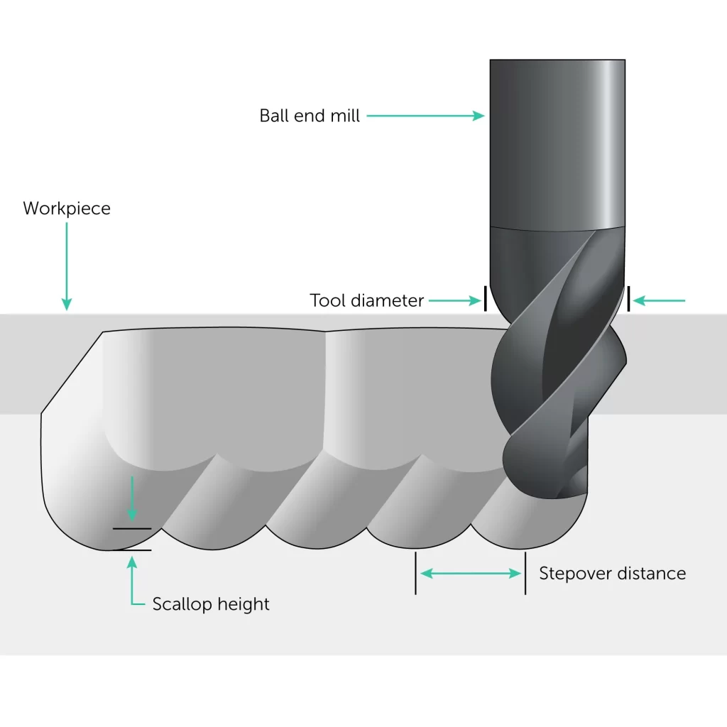
In CNC milling, “stepover” describes the lateral distance between consecutive toolpaths of a cutting tool. Typically, the recommended stepover is a percentage of the tool diameter. Machinists can input calculated stepover dimensions in computer-aided manufacturing (CAM) software or use built-in CNC stepover calculators. While experienced machinists may specify stepover based on past projects, a simple formula exists for CNC milling parts.
Calculating CNC Stepover
Stepover is usually expressed as a percentage of the tool diameter using the following formula:
Stepover = Tool Diameter × CNC Stepover Percentage
Follow these steps to calculate CNC stepover with example data:
- Determine the cutting tool diameter
For this example, we’ll use a 10 mm end mill. - Set the stepover percentage
- For roughing: Common range is 40% to 60% of the tool diameter. We’ll use 50%.
- For finishing: Range is typically 5% to 20% of the tool diameter. We’ll use 10%.
- Calculate the stepover
- Roughing with a 10 mm tool at 50% stepover:
Stepover = 10 mm × 0.50 = 5 mm - Finishing with a 10 mm tool at 10% stepover:
Stepover = 10 mm × 0.10 = 1 mm
- Roughing with a 10 mm tool at 50% stepover:
Why Stepover Matters in CNC Machining

Stepover affects surface finish, part quality, total machining time, and cost. Depending on priorities, parts may require smaller or larger stepover values:
- When surface finish is critical (e.g., high-visibility parts, precision molds, aerospace/medical/optical components), use smaller stepover (5–25% of tool diameter). Note that diminishing returns exist—extremely small stepover significantly increases machining time without proportional improvements in surface roughness (Ra). Balancing stepover with required roughness is key for efficiency.
- When machining efficiency is prioritized or surface finish is non-critical (e.g., large production runs, parts needing heavy material removal), use larger stepover (40–60% of tool diameter). Larger stepover removes material faster.
A common practice—especially for molds in the automotive industry—involves roughing with a larger stepover followed by finishing with a smaller stepover to balance efficiency and surface quality.
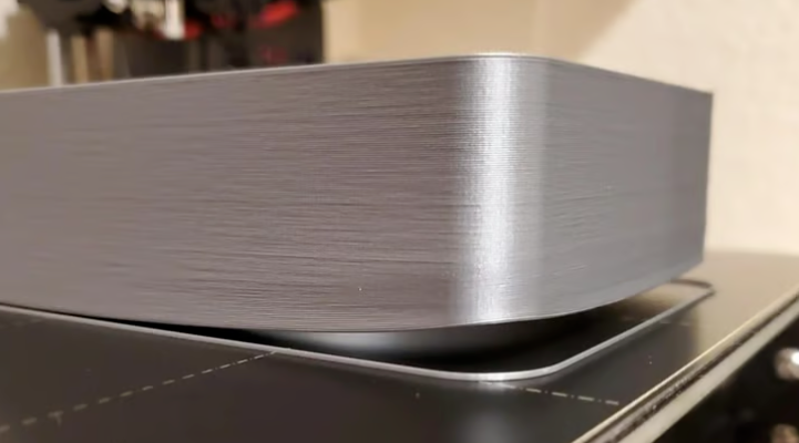
Smaller Stepover
A smaller stepover means less distance between consecutive toolpaths. This minimizes the height of peaks and valleys left by the tool, resulting in a smoother surface finish. Tool marks are less visible due to tighter overlap between passes. However, machining time increases, and material removal is slower.
Smaller stepover allows the tool to capture finer details and complex geometries—critical in finishing operations for high precision and intricate surfaces. Software developers must account for tool geometry, material properties, and machine capabilities to design toolpath algorithms that accurately machine these features.
Advantages:
- Improved surface finish (smaller gaps between toolpaths).
- Better capture of complex geometric details.
- Uniform distribution of tool wear across the cutting edge.
Disadvantages:
- Increased tool wear (more passes).
- Longer machining time, reducing efficiency—especially for harder materials where cumulative wear is significant.
Larger Stepover
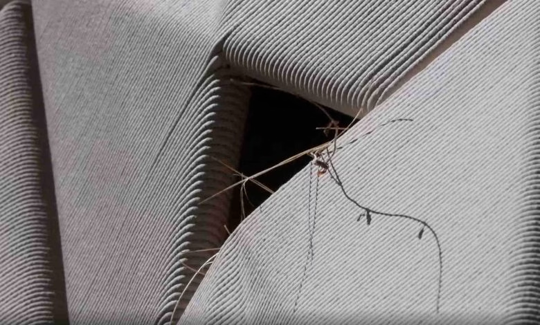
A larger stepover creates greater distance between toolpaths, resulting in higher peaks, deeper valleys, and more visible tool marks (a rougher texture). However, more material is removed per pass, and a subsequent smaller stepover can smooth the surface.
| Stepover | Surface Finish | Machining Efficiency |
|---|---|---|
| Smaller | Better | Lower |
| Larger | Rougher | Higher |
While larger stepover reduces total machining time, it may concentrate wear on a smaller portion of the cutting edge, shortening tool life—especially with hard materials or aggressive parameters. Balancing stepover with cutting speed and depth can optimize tool life while maintaining acceptable surface finish and efficiency.
What Is the Optimal CNC Stepover?

CNC machinists must balance surface finish and efficiency while considering workpiece material, tool diameter, and tool geometry:
Workpiece Material
Material thermal conductivity and heat resistance influence stepover:
- Plastics and composites: Prone to deformation from overheating. Smaller stepover disperses cutting forces across more passes, reducing heat.
- Metals and ceramics: Withstand higher temperatures, allowing larger stepover. However:
- Hard materials (stainless steel, titanium): Generate more wear/heat; smaller stepover minimizes tool load and improves surface finish.
- Soft materials (aluminum, brass): Less wear/heat; larger stepover speeds processing without sacrificing quality.
- Brittle materials (cast iron, ceramics): Susceptible to cracking; smaller stepover reduces cutting force to prevent breakage.
- Ductile materials (copper, plastics): Deform without cracking; larger stepover enhances efficiency.
Different materials may also require adjusted toolpaths (e.g., higher feed rates for soft materials, optimized coolant for hard materials).
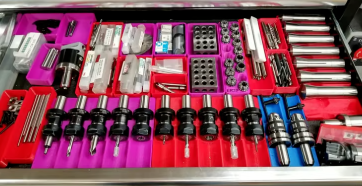
Tool Diameter
Tool diameter impacts heat, vibration, surface finish, and efficiency:
- Larger diameter tools: Have greater rigidity and heat dissipation, supporting larger stepover to reduce time while maintaining acceptable finish.
- Smaller diameter tools: Experience more heat/vibration; require smaller stepover to remove less material per pass, sacrificing efficiency for finer finishing.
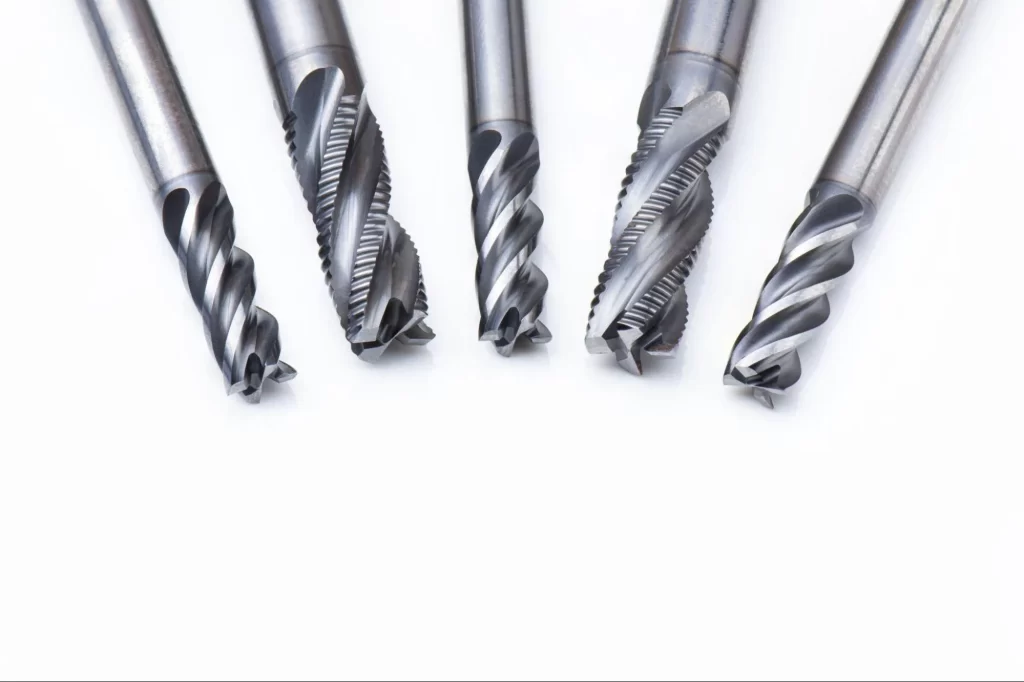
Tool Geometry
- Flat-end mills: Flat cutting surface allows larger stepover on planar surfaces but may need smaller stepover in corners.
- Ball-end mills: Spherical cutting surface requires smaller stepover, as cutting occurs only at the tip. Effective for curved surfaces but demands careful calculation to avoid inefficiency.
- Bullnose end mills: Rounded flat surface permits larger stepover on flats.
Applying Cutting Tool Stepover in CNC Machines
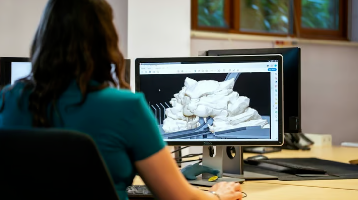
Machinists input stepover percentages in CAM software (e.g., Mastercam, Autodesk Fusion) to generate toolpaths. CAD models are imported into CAM software, which produces G-code defining tool movement (position, speed, direction). Stepover is critical alongside feed rate, spindle speed, and cutting depth. Toolpaths may be linear, rapid, circular, or zigzag.
Adaptive Stepover
Adaptive stepover uses algorithms to dynamically adjust stepover based on part geometry and cutting conditions. Ideal for complex parts, it ensures consistent cutting load, optimal material removal, extended tool life, and better surface finish. It balances efficiency and precision in irregular geometries or variable material thicknesses.
CNC Milling Stepover vs. Other CNC Operations
Stepover is specific to milling, but related concepts exist in other CNC processes:
- CNC turning: Equivalent to “depth of cut” (thickness of material removed per pass).
- CNC drilling: Similar to “peck depth” (distance the tool retracts to clear chips between cycles).
For more information, contact Debaolong Seiko. You are also welcome to upload your designs to Debaolong Seiko for a quote.