


1. Workpiece Overcut
Causes:
- Tool deflection due to insufficient strength, excessive length, or small size.
- Improper operation by the operator.
- Uneven cutting allowance (e.g., 0.5mm on curved sides and 0.15mm on the bottom).
- Inappropriate cutting parameters (e.g., too large tolerance, excessive SF setting).
Solutions:
- Tool selection principle: Use the largest possible tool with the shortest feasible length.
- Add corner clearing programs and maintain uniform allowances (keep side and bottom allowances consistent).
- Adjust cutting parameters reasonably, and round off corners with large allowances.
- Use the machine’s SF function for operators to fine-tune speeds for optimal cutting performance.
2. Centering Issues
Causes:
- Inaccurate manual operation by the operator.
- Burrs on the mold perimeter.
- Magnetism on the centering rod.
- Non-perpendicular mold edges.
Solutions:
- Double-check manual operations; center at the same point and height repeatedly.
- Remove burrs with an oilstone or file, wipe clean with a rag, and confirm by hand.
- Demagnetize the centering rod before use (consider ceramic centering rods).
- Check mold perpendicularity with a dial indicator; consult fitters for solutions if errors are significant.
3. Tool Setting Issues
Causes:
- Inaccurate manual operation by the operator.
- Improper tool clamping.
- Errors in fly cutter blade installation (fly cutters inherently have minor errors).
- Tolerances between R-end mills, flat-end mills, and fly cutters.
Solutions:
- Double-check manual operations; set tools at the same point repeatedly.
- Clean the tool shank with an air gun or rag before clamping.
- Measure the fly cutter arbor when installing blades; use a single blade for surface finishing.
- Create a separate tool setting program to avoid errors between R-end, flat-end, and fly cutters.
4. Collision – Programming
Causes:
- Inadequate safety height or no safety height set (G00 rapid feed causes tool/chuck to hit the workpiece).
- Mismatch between the tool listed on the program sheet and the actual program.
- Errors in tool length (cutting edge length) or machining depth on the program sheet.
- Mistakes in Z-axis zeroing values on the program sheet vs. actual settings.
- Incorrect coordinate system setup during programming.
Solutions:
- Measure workpiece height accurately to ensure the safety height is above the workpiece.
- Ensure tool information on the program sheet matches the actual program (use automated program sheets or images for clarity).
- Measure the actual machining depth on the workpiece; specify tool length and cutting edge length clearly (typically, the clamping length should exceed the workpiece by 2–3 mm, and the cutting edge should clear by 0.5–1.0 mm).
- Perform actual Z-axis zeroing on the workpiece and document values carefully (double-check manual entries).
5. Collision – Operator
Causes:
- Incorrect Z-axis depth setting.
- Errors in centering, touching off, or data input (e.g., single-side zeroing without accounting for tool radius).
- Using the wrong tool (e.g., using a D10 tool instead of D4).
- Running the wrong program (e.g., executing A9.NC instead of A7.NC).
- Mismatched handwheel direction during manual operation.
- Incorrect direction when using manual rapid feed (e.g., pressing +X instead of –X).
Solutions:
- Confirm the zeroing position (bottom, top, or analysis surface) when setting Z-axis depth.
- Double-check centering, touching off, and data input results.
- Cross-verify the tool with the program sheet and code before clamping.
- Run programs sequentially in order.
- Improve the operator’s proficiency in manual machine operations.
- Raise the Z-axis above the workpiece before moving rapidly in manual mode.
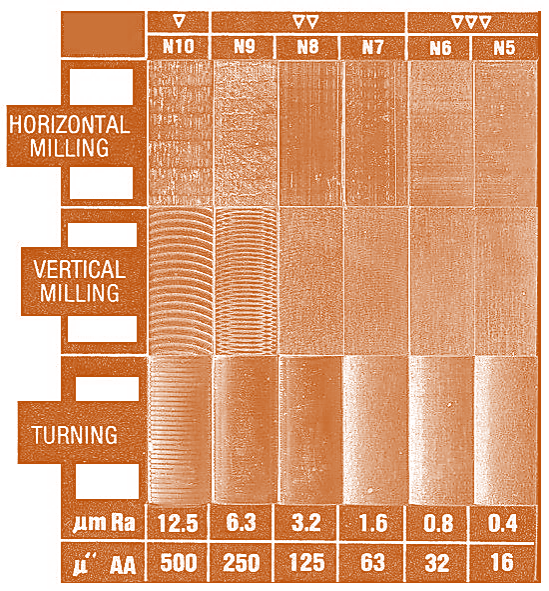
6. Surface Finish Accuracy
Causes:
- Unreasonable cutting parameters leading to rough surfaces.
- Dull tool edges.
- Excessive tool overhang or cutting edge extension.
- Poor chip evacuation, air blowing, or coolant flushing.
- Inappropriate tool path (consider climb milling where possible).
- Workpiece burrs.
Solutions:
- Optimize cutting parameters, tolerance, allowance, spindle speed, and feed rate.
- Regularly inspect and replace tools as needed.
- Minimize tool overhang during clamping; keep cutting edge extension to a minimum.
- Adjust spindle speed and feed rate appropriately for flat-end, R-end, and round-nose tools.
- Burrs are related to machine performance, tool condition, and tool paths. Understand the machine’s capabilities and perform touch-up passes on burr-prone edges.
For more information, contact Debaolong Seiko.