


Grooving in Manufacturing: Principles, Techniques, and Applications
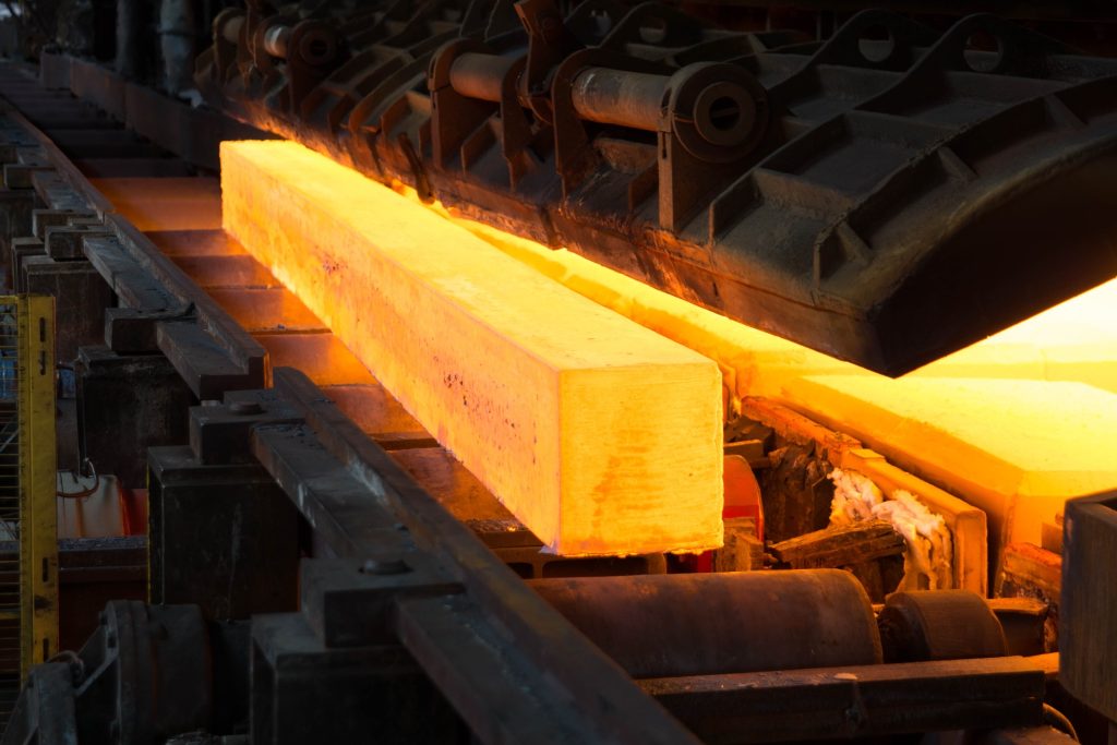
Grooving is commonly used in manufacturing to create precise recesses or notches in metal, enabling components like seals and O-rings to fit with exact precision. Grooving operations can produce various geometries in different sizes. Key parameters of this process include tool selection, material influence, feed rate, cutting speed, and depth of cut. By enhancing precision, versatility, and efficiency in end products, grooving forms the foundation of modern manufacturing processes.
What is Grooving in Machining?
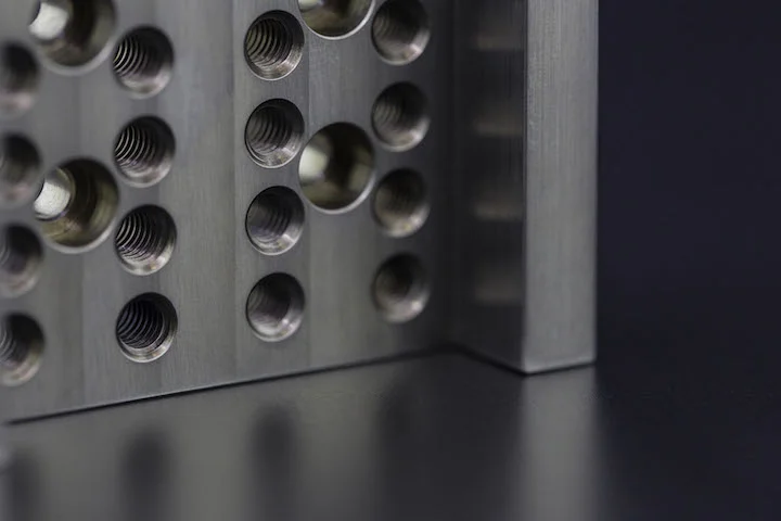
Grooving is a machining operation that creates narrow channels in a workpiece. It is typically performed on CNC machines using specialized cutting tools. Grooves provide paths for threads and ensure precise fits for O-rings and seals.
The Grooving Process
Grooving is a CNC turning process that forms long, narrow recesses in a workpiece. It allows other geometric features to move within the groove (e.g., channels cut into metal). The size of the cut depends on the width of the cutting tool; wider grooves require multiple tool passes.
Purpose of Grooving
Grooving facilitates part assembly or connection. For example, grooved pipes easily connect to sprinkler fittings and ensure secure piping connections regardless of internal water pressure. CNC machines, equipped with dedicated tools, are commonly used for grooving.
Grooving vs. Turning
Grooving and turning are distinct operations:
- Grooving creates narrow cuts with a depth equal to the cutting tool’s width.
- CNC turning removes material from a rotating workpiece to form cylindrical shapes.
Common Applications
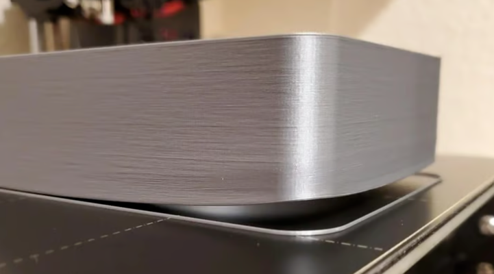
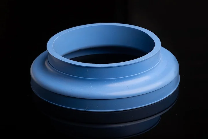
Grooving is widely used to manufacture rings, seals, and retaining grooves. It is also critical in fire safety systems (e.g., grooved flanges for HVAC duct connections) and applications like water treatment systems, metal plate seams in locked pipes, and barrels.
Overview of Grooving Machines
Grooving machines operate on a simple principle: rotating cutting tools form grooves in metal workpieces. They control groove angles and cutting depths to ensure precision, especially for sharp corners. CNC (Computer Numerical Control) systems automate grooving, enabling high precision via high-speed cutting tool selection.
Characteristics of Grooving Lathe Tools
Grooving tool features vary by type:
Types of Grooving Tools
- Facing Grooving Tools
These tools move along the workpiece surface on CNC lathes. Shorter cutting depths are preferred for stability. High-precision cutting fluids improve chip control and evacuation. - Internal Grooving Tools
These tools operate inside the workpiece. Cutting fluids are used to enhance flow, material removal, and chip control. Operations start from the rear of a hole and progress forward to facilitate chip ejection. - External Grooving Tools
These tools move radially along the workpiece’s outer surface, with material removal occurring at the cutting point.
Parting Tools vs. Grooving Tools
Parting tools separate a workpiece into two parts by cutting a narrow groove, while grooving creates channels on the workpiece surface.
Grooving Inserts
- Grooving Blades
Designed for machining deep, small holes with long overhangs. They are used when chatter or deflection is anticipated. - Carbide Inserts
Ideal for abrasive or corrosive materials like steel or cast iron. They handle semi-interrupted cuts and form imperfect holes in shafts. - Tungaloy Inserts
Heavy-duty inserts for roughing operations (e.g., forging, casting, and rough-sawn blanks).
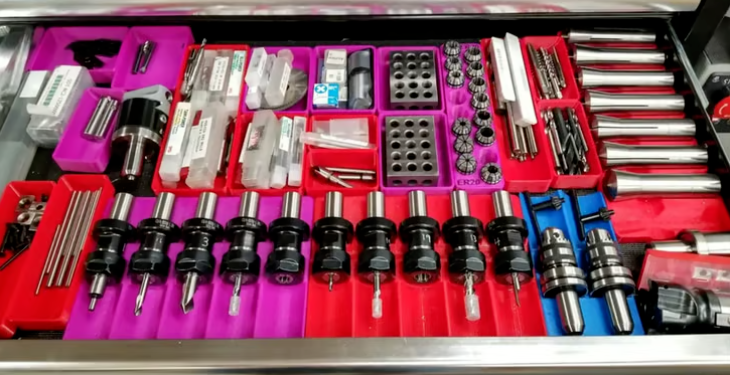
Cutting Tools and Tool Wear
Common cutting tools for grooving include hand mills, milling heads, circular saws, track saws, planers, crosscut chisels, and table saw blades. Tool wear—caused by high temperatures, improper parameters, or machining operations—leads to cutting tool failure.
Impact of Material on Grooving
Grooving results vary by material hardness and properties:
- Stainless Steel
Hard and prone to work hardening, causing tool wear. Grooving requires low cutting speeds. - Aluminum Sheets
Ductile and easily bent. Grooving is used for specialized designs unachievable with standard manufacturing methods. - Brass
Ductile and highly machinable, allowing high-speed cutting and superior surface finishes. - Titanium
Poorly machinable with low stress/strain ratios and elasticity, leading to potential deformation. Textured tools reduce friction and improve machinability. - ABS Plastic
Brittle with low heat resistance. Triangular milling chamfer tools (also used in woodworking) are effective for grooving. - Polycarbonate (PC)
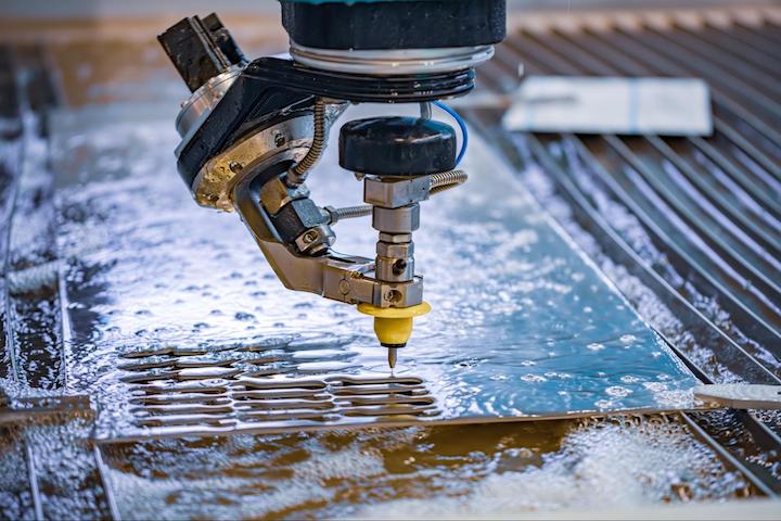
Non-toxic and impact-resistant. Grooving is done via engraving machines, grooving rollers, or laser cutting. - Polyoxymethylene (POM)
Used in applications requiring tight tolerances, high machinability, and low deformation. Grooves enhance adhesion to other materials. - PTFE
Grooving on PTFE resembles that on rubber (especially O-rings) but with narrower widths and lower pressure due to the material’s relative rigidity.
Material Hardness and Groove Quality
Groove quality is significantly affected by material hardness, depending on the groove type and welding process. For example:
- V-grooves can increase weld zone hardness by 33%.
- Smaller weld grooves enhance toughness and hardness.
- High heat input and slow cooling reduce hardness.
Electropolishing for Surface Finish
Electropolishing can be applied to surfaces with multiple grooves, improving surface finish by up to 50% without affecting dimensional tolerances. However, factors like tolerance and material removal rate also influence final finish.
Precision Grooving Techniques
Common practices for precision grooving include:
- Controlling Cutting Forces and Vibration
Secure workpiece clamping and proper positioning reduce vibration. Low feed rates and cutting speeds improve surface finish and groove quality; shallow cuts minimize forces and vibration. - Radial Depth of Cut
Measures tool contact with the material perpendicular to the axis (also called cutting width). Groove quality depends heavily on feed rate, cutting speed, and radial depth. - Maximizing Tool Efficiency
Select appropriate grooving tools and inserts based on material, groove geometry, and machining parameters. - Improving Groove Surface Finish
Achieved via proper tool selection, coolant use, optimized cutting speed/feed rate, tool geometry, wiper edge techniques, and avoiding thin, large cutting tools.
Grooving Operations on CNC Lathes
Steps for Lathe Grooving
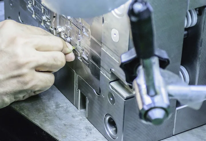
- Setting Up the CNC Lathe
Securely clamp the workpiece and mark the grooving position. - Adjusting Lathe Parameters for Quality
Select and calibrate the grooving tool, set up the CNC lathe, adjust RPM, input/run the program, and clean the setup after successful grooving.
External vs. Internal Grooving
- External Grooving: Cuts channels on the workpiece exterior, moving along the outer diameter.
- Internal Grooving: Cuts inside the workpiece, forming deep holes and cavities.
Deep Grooves: Challenges and Solutions
Deep grooving faces challenges like poor chip evacuation, limited coolant access, tool wear, and machine misalignment (causing tool deflection and rough finishes). Solutions include using flywheels to reduce vibration, optimizing tool design, lubrication, proper alignment, and regular bearing replacement.
Preventing Tool Wear in CNC Operations
To prevent wear: use correct cutting parameters, apply cutting fluids, select wear-resistant tool materials, and monitor tool condition regularly.
Troubleshooting Grooving Issues
- Chip Control Solutions
Use high-flow coolant, non-linear tool paths, side adjustments, speed optimization, small rods, narrow inserts, clamping, thick inserts, and large-diameter tools. - Managing Tool Vibration
Use dual-contact spindles and tool holders to reduce vibration and improve groove precision. - Adjusting Surface Finish
Use high-speed cutting tools, proper retraction, optimal tool nose radius, wiper inserts, eliminate dwells, and use tools with large rake angles. - Reducing Tool Chatter and Wear
Use rigid tools/holders, short tool overhangs, low cutting forces/depths, anti-vibration bars, and allow machine arcs.
5 Precision Grooving Techniques
- Deep Facing Grooving
Creates grooves up to 20–25 mm deep, aligned axially with the workpiece, typically on part end faces. - Achieving Smooth External Grooves
Critical for shafts and pipes. Requires good surface finish for compartment fits; wide grooves need multiple passes. - Optimizing Groove GeometryGroove FeatureParameterPosition0.2–0.5℃axWidth0.2–0.4℃axAngle60°
- Multi-Edge Grooving Inserts
Suitable for diverse operations: CNC turning, grooving, threading, profiling, and parting. - Custom Grooving Tool Configurations
Used for unique designs unachievable with standard tools, reducing cycle times, enabling angled cuts, and simplifying programming.
How to Select the Right Grooving Tool
Consider: material type, groove shape, chip control, machine settings, and insert width.
Key Considerations
- Tool Material
Choose carbide or Tungaloy based on material, cutting conditions, holder compatibility, groove geometry, diameter range, and budget. - Tool Compatibility and Geometry
Ensure compatibility with the workpiece material; adjust geometry (cutting edge, rake angle, clearance angle) for better chip removal and finish. - Choosing Between Internal and External Tools
Depends on tool size/shape, material, grooving method, coolant type, feed rate, and cutting control. - Matching Tool to Workpiece Material
Hard materials require durable tools (e.g., carbide); ductile materials can use high-carbon steel or less durable tools. - Tools for Different Grooving Operations
Options include parting tools, threading tools, CNC turning tools, O-ring inserts, small internal grooving tools, and knurling tools.
Improving Grooving Efficiency and Quality
- Optimizing Feed Rate and Cutting Speed
Start with low feed rates, gradually increasing to improve chip control. Adjust cutting speed with feed rate to extend tool life. - Ensuring Consistent Groove Sizes
Measure with rulers or calipers; use O-Sizers or Pi-Tapes for large inner diameters. O-ring calculators (e.g., ERIKS, Ceetak) aid precision. - Reducing Tool Wear via Proper Setup
Optimize parameters, use coolants/lubricants, lower cutting speed, avoid re-cutting chips, and control deflection. - Using Cutting Fluids for Better Results
Fluids reduce friction, extend tool life, and enhance cutting precision. - Enhancing Groove Surface Finish
Use inserts with precise geometry and wiper edges, tight tolerances, correct radius/width, and proper profiling/chamfering for mass production.
FAQs About Grooving Machining
- What is the difference between a groove and a recess?
A groove is a straight, long channel with radiused edges; a recess is a cylindrical indentation with cuts on the outer/inner diameter. - Which machines are used to cut grooves in metal?
CNC machining centers, lathes, milling machines, grooving machines, and gear cutters. - How to prevent tool chatter during grooving?
Use rigid tools/holders and apply consistent tool pressure. - What materials are best for grooving tools?
Carbide inserts, due to high wear resistance, heat resistance, and versatility across materials. - How to improve groove surface finish?
Use high cutting speeds, balanced tools to reduce vibration, machines with good damping, chip breakers, and wiper edges. - Do grooving tools require coatings for better performance?
Yes, coatings extend tool life, reduce cycle times, and improve surface finish.
For more information, contact Debaolong Seiko. You are also welcome to upload your designs to Debaolong Seiko for a quote.