


If your designs are becoming increasingly complex, this guide will provide a clear, structured approach to ensure parts are produced to specifications while avoiding unnecessary costs and delays. You will learn how to evaluate design complexity, identify optimization opportunities, and collaborate effectively with manufacturers to ensure parts meet requirements.
CNC machining excels at producing complex parts due to its advanced capabilities, including multi-axis operations, precision tools, and integration with sophisticated software. These features enable it to machine complex geometries, internal cavities, and undercuts that are difficult or impossible to achieve with traditional methods.
From aerospace turbine blades with intricate cooling channels to custom orthopedic implants in healthcare, and precision enclosures for electronics, CNC machining drives innovation across industries by delivering accuracy and efficiency. Its ability to seamlessly switch cutting tools and leverage CAD/CAM systems ensures high precision and adaptability, making it ideal for both prototype development and mass production.
This guide offers a comprehensive approach to tackling the challenges of machining complex parts. It will help you assess design complexity, uncover optimization potential, and implement strategies to simplify production. By following these steps, you can meet specifications efficiently while minimizing costs and avoiding production delays.
Step 1: Is Your Design Truly Complex?
Before seeking solutions, evaluate whether the part is genuinely complex or if simplification is possible. Use the following checklist:
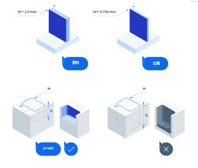
- Does the part have thin walls or tall, slender structures?
Thin walls (metal <0.8mm thick or plastic <1.5mm thick) are prone to deformation and may require specialized fixtures or reduced cutting speeds. - Does it include deep holes?
Holes with an aspect ratio exceeding 3:1 can cause tool deflection, heat buildup, and chip evacuation issues. - Are there hard-to-reach internal cavities or undercuts?
These structures require long-reach tools, multi-axis machining, or alternative processes like EDM, increasing costs and lead times. - Does it involve complex curved geometries?
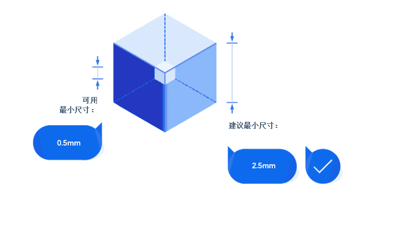
Curved surfaces or intricate profiles typically require advanced programming, 5-axis machines, and multiple operations, extending machining time and costs. - Are there micro-scale features or extremely small fillets?
Features smaller than 2.5mm or sharp internal corners demand specialized tools and techniques, increasing complexity and tool wear. - Is the part large in size?
Large parts (usually >1000mm or exceeding standard CNC machine work envelopes) require specialized equipment, robust fixtures, and careful handling. Thermal expansion and accelerated tool wear necessitate temperature control and frequent tool changes. - Are there interrupted cuts or narrow slots?
Uneven tool contact or narrow slots can cause wear and surface quality issues, requiring meticulous toolpath planning. - Does the full dimension have strict tolerances?
Applying tight tolerances universally increases costs and time. It is recommended to restrict high-precision requirements to critical features only.
If you checked multiple items—congratulations—you do have a complex part! But don’t worry. We’ll explore how to optimize the design and simplify manufacturing while preserving functionality.
Material selection also affects machining difficulty: High-hardness materials like titanium alloys or hardened steel accelerate tool wear and require reduced cutting speeds; high-toughness or low-thermal-conductivity materials like stainless steel demand special chip evacuation and heat dissipation strategies. Material rigidity may also increase tool loads and vibration, requiring enhanced fixturing.
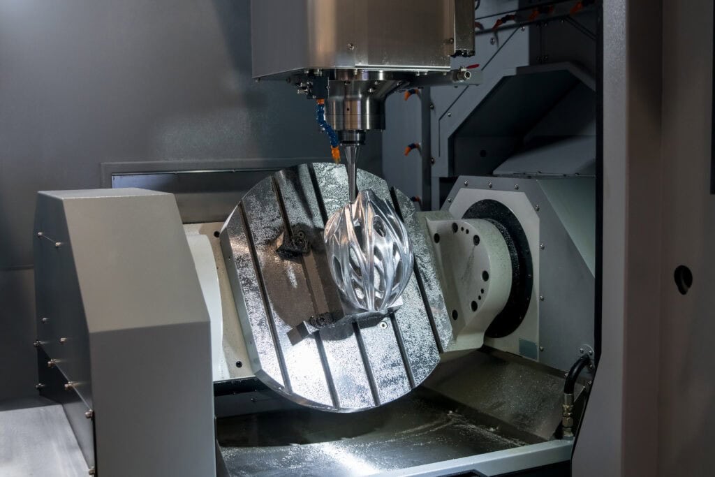
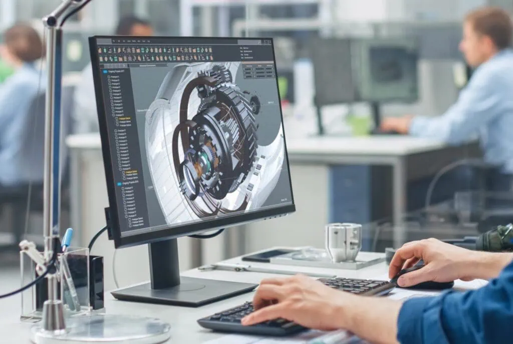
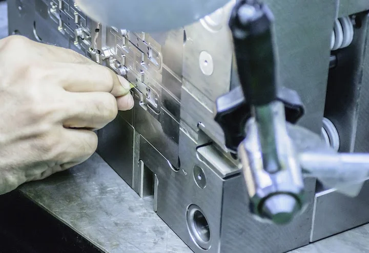
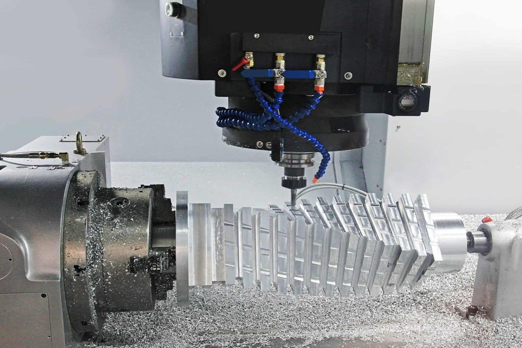
5-Axis High-Speed Machining Center for Metalworking
Step 2: Can Your Design Be Optimized?
After confirming part complexity, the next step is to optimize the design for manufacturability. Below are actionable recommendations and software tools to simplify production while maintaining functionality:
1. Simplify Wall Thickness and Deep Cavity Features
Excessively thin walls (below recommended values) are prone to deformation under cutting forces, leading to precision deviations and tool damage. Deep cavity features cause limited tool accessibility, poor chip evacuation, and heat buildup—all increasing machining time and risk. Simplifying these features improves material stability, reduces tool wear, and enhances efficiency.
Practical steps:
- Set minimum wall thicknesses: 0.8mm for metals and 1.5mm for plastics to avoid deflection.
- Keep cavity depth-to-width ratios within 3:1 for better accessibility and clearance.
- Use CAD software like SolidWorks or Autodesk Fusion 360 for simulation and optimization.
2. Optimize Complex Geometries and Surface Features
Complex geometries (e.g., free-form surfaces or curved profiles) require 5-axis machines and multiple operations, increasing time and costs. Machining such features also causes higher tool wear and requires specialized programming, reducing cost-effectiveness.
Practical steps:
- Replace overly complex features with simpler geometries where possible.
- Avoid embossed logos or decorative elements in early stages—add them during post-processing to reduce material removal and machining time.
- Use CAM software like HyperMill or Mastercam to generate efficient toolpaths, minimizing setup changes and improving precision.
3. Reduce Internal Cavities and Hard-to-Reach Features
Internal cavities and recessed structures restrict tool movement, making them difficult to machine with standard tools. Such features often require custom tools, additional setups, or alternative processes (e.g., EDM), increasing costs and lead times.
Practical steps:
- Split the part into modular components, machine them separately, then assemble.
- For unavoidable internal cavities, use extended tools and optimize machining strategies via Fusion 360.
- For extremely hard-to-machine areas, consider non-traditional methods like EDM.
4. Avoid Minuscule Features
Features smaller than 2.5mm are challenging for standard CNC tools. Machining them requires micro-tools (which wear quickly) and reduced spindle speeds. Additionally, ultra-precise micro-features often demand advanced inspection and verification, further increasing complexity.
Practical steps:
- Redesign the part to eliminate sub-2.5mm micro-features where feasible.
- Validate the functionality of the redesigned structure using simulation tools like Siemens NX or SolidWorks.
- For unavoidable micro-features, use specialized processes like micro-EDM or laser cutting instead of traditional methods.
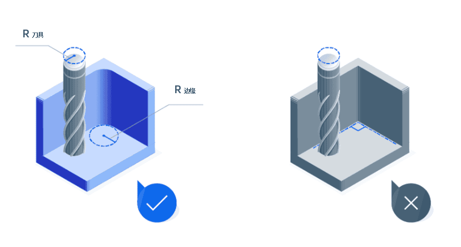
5. Maintain Consistent Internal Fillet Radii
Sharp internal corners require smaller tools, which are more prone to breakage and wear. Inconsistent radii also create stress concentration points, potentially weakening the part. Consistent radii enable smoother cutting, reduce tool wear, and improve machining efficiency and part durability.
Practical steps:
- Design corners with arc radii of at least 130% of the tool radius.
- Use Fusion 360’s built-in design rules to automatically adjust corner radii for manufacturability.
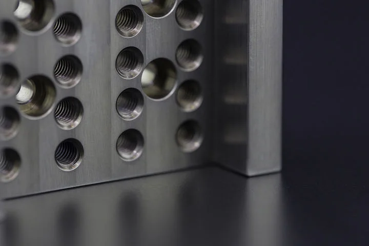
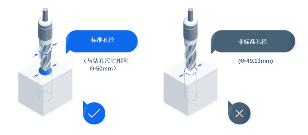
6. Choose Standard Hole Sizes, Thread Lengths, and Rational Hole Layouts
Non-standard hole sizes, excessively long threads, and poor hole positioning increase machining time and complexity. Ensuring proper alignment and following industry standards simplifies tool requirements, improves accessibility, and reduces costs.
Practical steps:
- Adopt standard hole and thread specifications; limit thread length to 1.5 times the diameter for optimal efficiency.
- Align holes along machine axes to optimize tool accessibility and reduce deflection.
- Avoid drilling near edges or thin walls to prevent deformation.
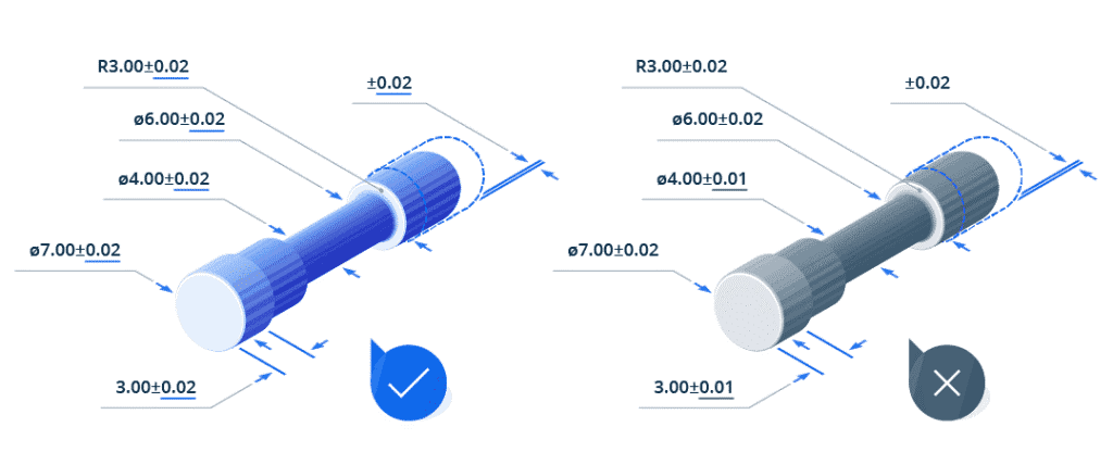
7. Apply Tolerances Selectively
Tight tolerances across the entire part—even on non-critical features—increase machining time, tool wear, and inspection costs, significantly raising production expenses. Restricting strict tolerances to functional or critical areas ensures necessary precision while saving time and costs elsewhere.
Practical steps:
- Apply tight tolerances (e.g., ±0.01mm) only to mating/critical surfaces or alignment points.
- Use standard tolerances (e.g., ISO 2768 medium or fine grades) for non-critical areas.
- Analyze and optimize tolerance 标注位置 using GD&T tools in Creo or SolidWorks.
Step 3: How to Assist Manufacturers?
By ensuring clear, manufacturable design documentation, you can reduce errors and delays. Additionally, understanding manufacturers’ capabilities (e.g., their expertise with different materials and machine types) helps you make informed design decisions. This approach not only improves project efficiency but also ensures the final part meets your specifications.
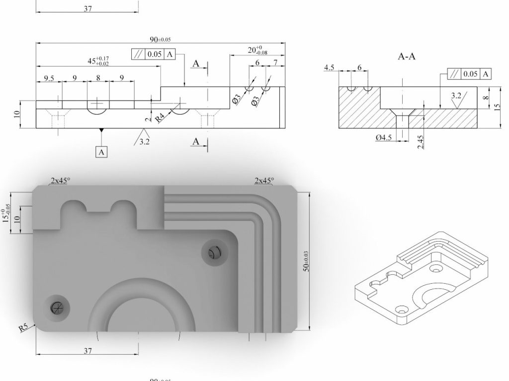
Provide Complete CAD Models
CAD models are the blueprint for manufacturing. Ambiguous or missing dimensions, tolerances, or annotations force manufacturers to make assumptions, risking errors or delays. To ensure precision and efficiency:
- Include all relevant details, such as tolerances, material thicknesses, and surface treatment requirements.
- Clearly 标注 critical features like threads, mating surfaces, or post-processing areas.
- Use compatible formats (e.g., STEP or IGES) for easy import into CNC programming software.
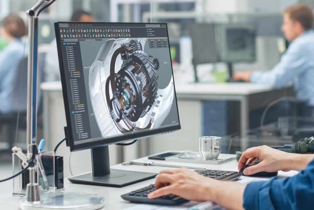
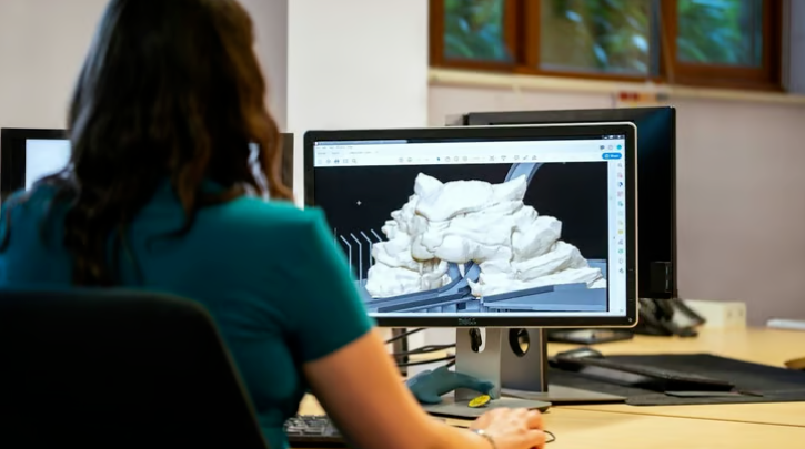
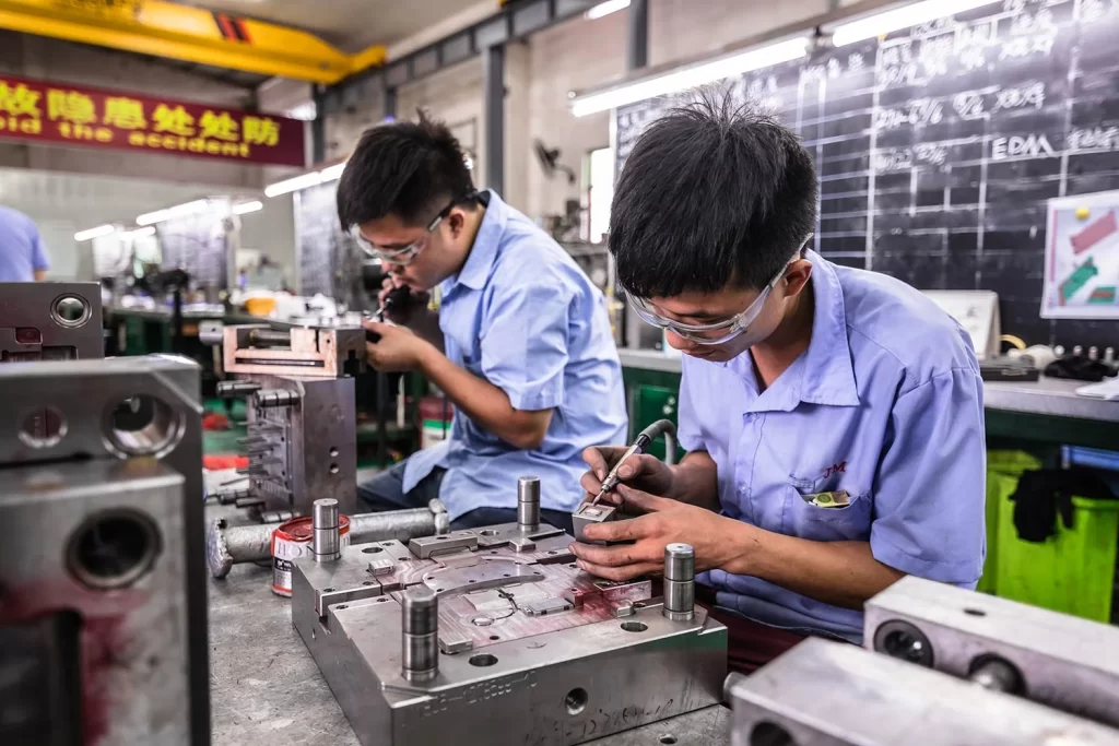
Engineers Using CAD Software to Design Mechanical Components
Use Standard Features Where Possible
Complex CNC-machined parts often have intricate geometries, tight tolerances, multi-material combinations, and sometimes large sizes, requiring multi-axis machining and advanced processes. The table below outlines key complexity factors in CNC machining, explaining their impact on design, manufacturability, costs, and overall difficulty.
| Complexity Factors | Impact on Design | Impact on Manufacturability | Cost Impact | Machining Difficulty |
|---|---|---|---|---|
| Slender Structures | High | Medium | Increase fixture costs | High – Deflection risk |
| Complex Surface Geometry | Very High | High | Increase programming costs | High – Require multi-axis tool machining |
| Deep Holes | Medium | High | Special tooling costs | High – Chip evacuation issues |
| Internal Threads | Medium | Medium | Higher tool replacement costs | Medium – Hard to access |
| Multi-Material Parts | High | Very High | Vary based on material properties | Medium – Hard to access |
| Micro Features | Very High | High | Higher due to tool changes | Very High – Tool wear issues |
| Interrupted Cuts | Low | Medium | Slightly increase | Medium – Uneven tool engagement |
| Hard-to-Access Internal Cavities | High | Very High | Custom tooling requirements | Very High – Movement clearance |
| Thin Grooves or Slots | Medium | Medium | Higher due to risk transfer | High – Difficult chip evacuation |
Step 4: What Are the Best Alternatives to CNC Machining for Complex Parts?
While CNC machining is versatile and efficient, some complex parts or geometries may be difficult or inefficient to produce using only CNC technology. In such cases, consider alternative techniques better suited to specific challenges. Below are key alternatives when CNC machining reaches its limits:
| Technology | Description | Advantages |
|---|---|---|
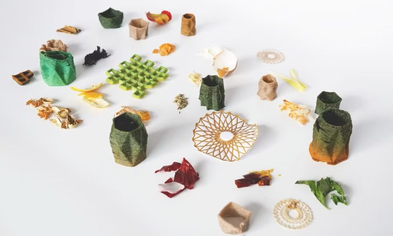
| Additive Manufacturing (3D Printing) | Builds parts by layer-by-layer material deposition, ideal for highly complex and intricate structures. | Suitable for complex internal structures, lightweight parts, and rapid prototyping. Includes multiple technologies (e.g., MJF, SLA), each with unique benefits. |
| Electrical Discharge Machining (EDM) | Removes material via electrical discharges, excelling at hard materials and complex details. | Particularly effective for sharp edges, deep cavities, or hard-to-reach features. |
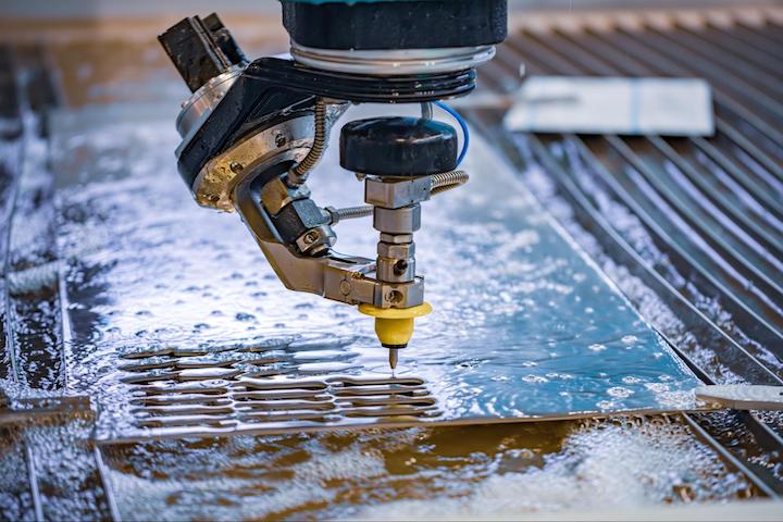
| Hybrid Manufacturing (e.g., CNC + Laser Cutting) | Combines CNC machining with laser or plasma cutting to produce parts with precise geometries and complex cutouts. CNC handles milling and forming; laser/plasma cutting for high-precision cutting or profiling. | Offers greater flexibility for complex contours by merging high-precision machining with efficient cutting. Reduces manufacturing steps and lead times by integrating multiple processes into one workflow. Suitable for parts needing fine cutting and high-precision machining. |
| Casting | Pours molten material into molds to form the desired shape. | Cost-effective for mass production and can achieve complex internal cavities. |
As shown, additive manufacturing excels at complex internal structures, while EDM and laser cutting are better for precision hard-to-reach features. Casting is ideal for mass-producing complex parts, and hybrid manufacturing flexibly combines multiple technologies. By understanding the strengths and limitations of these alternatives, engineers can choose the best approach to efficiently produce complex components.
For more information, please contact Debaolong Seiko. You are also welcome to upload your design to Debaolong Seiko for a quotation.