


Selecting the appropriate tolerances is critical for any engineering project, as it determines the future applicability, delivery time, and cost of the project.
Designers and engineers add tolerances to drawing specifications to ensure that the dimensions and geometric shapes of components are controlled. However, adding tolerances to each individual feature of a component is both time-consuming and inefficient. Therefore, using certain standardized tolerance values has become standard practice (learn more about tolerances in CNC machining).
In Europe and many other regions worldwide, these values are defined by ISO tolerance standards. These standards specify tolerance values for the geometric shapes of different parts and further classify them into different grades and categories to meet varying quality requirements.
Tolerance standards typically reduce the workload for designers. Instead of calculating tolerances for every geometric shape and feature in the model, designers can simply select the appropriate standard that matches the required quality grade.
European tolerance standards
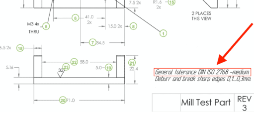
Tolerance standards vary depending on the manufacturing process. For example, European engineers commonly use tolerance standards defined by ISO 2768 and ISO 286 in subtractive manufacturing (such as CNC machining). At Debaolong seiko, we offer five options:
- ISO 2768 – Fine
- ISO 2768 – Medium
- ISO 286 – Grade 6
- ISO 286 – Grade 7
- ISO 286 – Grade 8
The main difference between ISO 286 and ISO 2768 is that ISO 2768 covers general tolerance ranges for linear and angular dimensions, while ISO 286 covers general tolerance ranges for cylindrical and parallel surfaces, such as shaft and hole systems. If a design includes features covered by both standards, these tolerance standards can be applied in parallel.
![]()
| Tolerance Standard | General Linear Tolerances | General Tolerances for External Radius and Chamfer Heights | Angular Dimensions |
| ISO 2768 – Medium (Standard) | ±0.1-2 mm depending on the nominal length from 0.5 to over 4000 mm | ±0.2-1 mm depending on the nominal length from 0.5 to over 6 mm | ±1°-0°5’ depending on the nominal length from up to 10 to over 400 mm |
| ISO 2768 – Fine | ±0.05-5 mm depending on the nominal length from 0.5 to over 2000 mm | ±0.2-1 mm depending on the nominal length from 0.5 to over 6 mm | ±1°-0°5’ depending on the nominal length from up to 10 to over 400 mm |
| ISO 286 – Grade 8 | Standardized tolerance value ranges from 0.014 to 0.33 mm depending on the nominal size from up to 3 to over 2500 mm | ||
| ISO 286 – Grade 7 | Standardized tolerance value ranges from 0.01 to 0.21 mm depending on the nominal size from up to 3 to over 2500 mm | ||
| ISO 286 – Grade 6 | Standardized tolerance value ranges from 0.006 to 0.135 mm depending on the nominal size from up to 3 to over 2500 mm | ||
ISO 2768
ISO 2768 and its derived geometric tolerance standards primarily apply to parts manufactured through machining or other material removal processes.
ISO 2768 applies only to drawings with the following characteristics. These are used when such features are not individually marked with custom tolerances:
- Linear dimensions (outline dimensions, internal diameter dimensions, diameters, distances, chamfer heights, radii)
- Angular dimensions
- Linear and angular dimensions resulting from parts assembled by mechanical processing.
Linear dimensions
| Nominal Length (mm) | Tolerance Class Values (mm) | ||
| Above | Up to and including | Fine | Medium |
| 0.5 | 3 | ±0.05 | ±0.1 |
| 3 | 6 | ±0.05 | ±0.1 |
| 6 | 30 | ±0.1 | ±0.2 |
| 30 | 120 | ±0.15 | ±0.3 |
| 120 | 400 | ±0.2 | ±0.5 |
| 400 | 1000 | ±0.3 | ±0.8 |
| 1000 | 2000 | ±0.5 | ±1.2 |
| 2000 | 4000 | – | ±2.0 |
External Radius and Chamfer heights
| Nominal Length (mm) | Tolerance Class Values (mm) | ||
| Above | Up to and including | Fine | Medium |
| 0.5 | 3 | ±0.2 | ±0.2 |
| 3 | 6 | ±0.5 | ±0.5 |
| 6 | above | ±1.0 | ±1.0 |
Angular Dimensions
| Nominal Size (mm) | Tolerance Class Values (°,ˈ ) | ||
| above | Up to and including | Fine | Medium |
| – | 10 | ±1° | ±1° |
| 10 | 50 | ±0°30ˈ | ±0°30ˈ |
| 50 | 120 | ±0°20ˈ | ±0°20ˈ |
| 120 | 400 | ±0°10ˈ | ±0°10ˈ |
| 400 | Above | ±0°5ˈ | ±0°5ˈ |
ISO 286
ISO 286 applies to subtractive manufacturing methods and specifies linear dimensional tolerances for the following types of features:
- Cylindrical
- 2 parallel opposite surfaces
This tolerance applies only to drawings containing these features. It is used when these features are not individually marked with custom tolerances. We offer three quality grades according to the ISO 286 standard: Grade 6 (IT6), Grade 7 (IT7), and Grade 8 (IT8).
ISO 286 selects standardized tolerance grades suitable for general purposes from a wide range of possibilities.
The following terms apply according to ISO 286:
- Nominal dimension: This is the feature dimension defined in the drawing specifications
- Actual dimension: This is the dimension obtained by measurement
- Upper limit of dimension: This is the maximum dimension allowed for the feature
- Lower limit of dimension: This is the minimum dimension allowed for the feature
- Tolerance: The difference between the upper limit of dimension and the lower limit of dimension.
| Nominal Size (mm) | Standard Ranges of Tolerance Grade | |||
| Above | Up to and including | IT6 | IT7 | IT8 |
| – | 3 | 0.006 | 0.010 | 0.014 |
| 3 | 6 | 0.008 | 0.012 | 0.018 |
| 6 | 10 | 0.009 | 0.015 | 0.022 |
| 10 | 18 | 0.011 | 0.018 | 0.027 |
| 18 | 30 | 0.013 | 0.021 | 0.033 |
| 30 | 50 | 0.016 | 0.025 | 0.039 |
| 50 | 80 | 0.019 | 0.030 | 0.046 |
| 80 | 180 | 0.022 | 0.035 | 0.054 |
| 120 | 180 | 0.025 | 0.040 | 0.063 |
| 180 | 250 | 0.029 | 0.046 | 0.072 |
| 250 | 315 | 0.032 | 0.052 | 0.081 |
| 315 | 400 | 0.036 | 0.057 | 0.089 |
| 400 | 500 | 0.040 | 0.063 | 0.097 |
| 500 | 630 | 0.044 | 0.070 | 0.110 |
| 630 | 800 | 0.050 | 0.080 | 0.125 |
| 800 | 1000 | 0.056 | 0.090 | 0.140 |
| 1000 | 1250 | 0.066 | 0.105 | 0.165 |
| 1250 | 1600 | 0.078 | 0.125 | 0.195 |
| 1600 | 2000 | 0.092 | 0.150 | 0.230 |
| 2000 | 2500 | 0.110 | 0.175 | 0.280 |
| 2500 | 3150 | 0.135 | 0.210 | 0.330 |
Equivalent to U.S. standards
The tolerance standards adopted by Europe (ISO) have corresponding equivalent standards in the United States (ASME). There are some differences between the ISO and ASME tolerance standards.
The following table lists some of the equivalent U.S. standards for European tolerance standards.
| Standard | ISO 2768 (fine) | ISO 2768 (medium) | ISO 268 grade 6 | ISO 268 grade 7 | ISO 268 grade 8 |
| Equivalent US standard | – | – | ASME B4.1 Grade 6 | ASME B4.1 Grade 7 | ASME B4.1 Grade 8 |
Conclusion
These tolerance standards are used to replace custom tolerances. Please upload your model to our instant quote engine for CNC machining and select one of the grades and categories from the list. If your parts require custom tolerances, please upload the corresponding part drawings at the same time.